Simple Simulation
Note
Read also: Simple RVE-type Simulation
A polycrystal containing 20 grains, generated and meshed by Neper, is used:
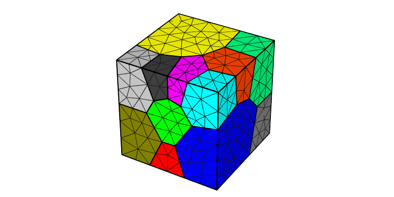
The domain is a unit cube. Length units are assumed to be mm, thus, all pressure units assumed to be MPa for the simulation (including input parameters). An FCC material with Anisotropic Elasticity and the Base Model for plasticity is considered, with the following material parameters:
\(C_{11}\) [MPa] |
\(C_{12}\) [MPa] |
\(C_{44}\) [MPa] |
\(m\) [-] |
\(\dot{\gamma_0}\) [1/s] |
\(h_0\) [MPa] |
\(g_0\) [MPa] |
\(g_s\) [MPa] |
|---|---|---|---|---|---|---|---|
\(245.0 \times 10^3\) |
\(155.0 \times 10^3\) |
\(62.5 \times 10^3\) |
0.05 |
1.0 |
200.0 |
210.0 |
330.0 |
The polycrystal is deformed in tension along the \(z\) direction up to 1% strain, at a rate of 0.001 \(\text{s}^{-1}\), using simple velocity conditions (\(v_z=0\) on z0 and \(v_z=0.001\) on z1, with additional constraints to avoid rigid-body motions). The stress-strain information, and the the nodal coordinates, the elemental orientations, stresses and strains, and the surface forces at final time (\(t = 10\text{ s}\)) are written to file.
Input Files
Execution
In the simulation directory (simple_simulation):
$ mpirun -np 4 fepx

 ==========================     F   E   P   X   ==========================
 Info   : A finite element software package for  polycrystal plasticity.
 Info   : Version 2.0.0
 Info   : Running on 4 cores.
 Info   : <https://fepx.info>
 Info   : Copyright (C) 1996-2023, DPLab, ACME Lab, CNRS.
 Info   : ---------------------------------------------------------------
 Info   : Start time: 2023-12-1 at 14:03
 Info   : Loading simulation...
 Info   :   [i] Parsing file `simulation.cfg'...
 Info   :   - Material parameters:
 Info   :     > Number of phases: 1
 Info   :     > phase 1 - crystal type:   fcc
 Info   :     > m:               0.500000E-01
 Info   :     > gammadot_0:      0.100000E+01
 Info   :     > h_0:             0.200000E+03
 Info   :     > g_0:             0.210000E+03
 Info   :     > g_s0:            0.330000E+03
 Info   :     > n:              -0.100000E+01
 Info   :     > c11:             0.245000E+06
 Info   :     > c12:             0.155000E+06
 Info   :     > c44:             0.625000E+05
 Info   :   [i] Parsed file `simulation.cfg'.
 Info   :   [i] Parsing file `simulation.msh'...
 Info   :   - Mesh parameters:
 Info   :     > Node number: 4008
 Info   :     > Elt  number: 2453
 Info   :   [i] Parsed file `simulation.msh'.
 Info   : Initializing simulation...
 Info   :   - Initializing fields from isotropic viscoplastic solution
 Info   :     > solveit_vp: Iteration 1
 Info   :       . Solving NL iteration... R = 0.4267E-01 (490 iters)
 Info   :     > solveit_vp: Iteration 2
 Info   :       . Solving NL iteration... R = 0.1751E-01 (489 iters)
 Info   :     > solveit_vp: Iteration 3
 Info   :       . Solving NL iteration... R = 0.1167E-01 (489 iters)
 Info   :     > Converged in 3 iterations
 Info   : Running step 1...
 Info   :   - Increment 1: t = 1.0000 secs, dt = 1.0000 secs
 Info   :     > solveit_evp: Iteration 1
 Info   :       . Solving SA iteration... R = 0.4928E+00 (622 iters)
 Info   :     > solveit_evp: Iteration 2
 Info   :       . Solving SA iteration... R = 0.2405E-03 (625 iters)
 Info   :     > Converged in 2 iterations

 [...]

 Info   : Elapsed time:    25.044 secs.
 Info   : Final step terminated. Simulation completed successfully.
 ========================================================================
The content of the resulting Simulation Directory (.sim), simple_simulation.sim, is:
simple_simulation.sim
├── inputs
│   ├── simulation.cfg
│   └── simulation.msh
└── results
  ├── elts
  │   ├── ori
  │   │   ├── ori.step0
  │   │   └── ori.step1
  │   ├── strain
  │   │   ├── strain.step0
  │   │   └── strain.step1
  │   ├── stress
  │   │   ├── stress.step0
  │   │   └── stress.step1
  └── nodes
      └── coo
          ├── coo.step0
          └── coo.step1
Simulation Results
The stress-strain curve can be plotted from the post.force.z1 file:
$ gnuplot plot_stress_strain.gp
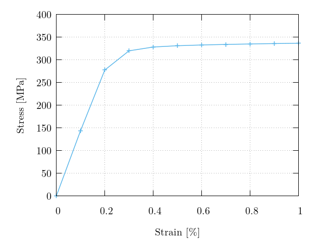
Macroscopic stress-strain curve recovered from the surface-integrated forces in post.force.z1. Markers denote values output at each increment.
The results can be plotted using Neper:
$ neper -V simple_simulation.sim -step 1 -showtess 1 -showcell 0 -showedge "domtype==1" -dataedgerad 0.005 -dataedgetrs 0.5 -datanodecoofact 10 -showelt1d all -dataelt1drad 0.005 -dataelt3dedgerad 0.0025 -dataelt3dedgecol 32:32:32 -imagesize 800:400 -datanodecoo coo -dataeltcol strain33 -dataeltscale 0.005:0.015 -dataeltscaletitle "Strain [-]" -print strain -dataeltcol stress33 -dataeltscale 200:400 -dataeltscaletitle "Stress [MPa]" -print stress
$ convert strain.png strain-scale3d.png -gravity East -composite deformed_mesh_strain.png
$ convert stress.png stress-scale3d.png -gravity East -composite deformed_mesh_stress.png
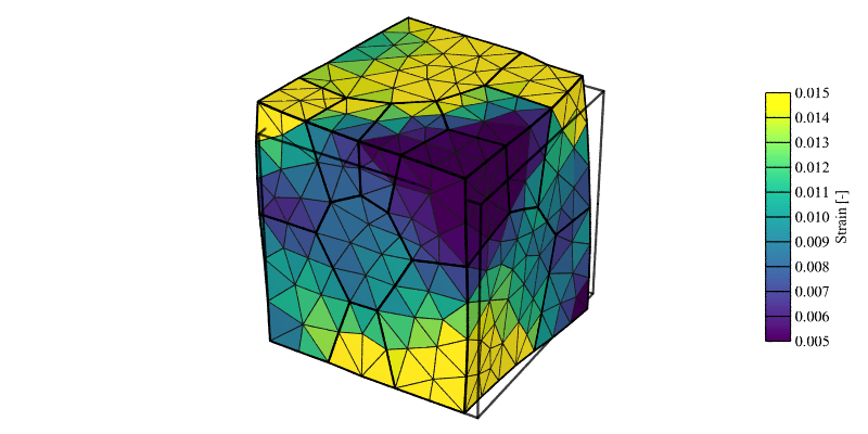
Strain field (\(\epsilon_{33}\)) at 1% axial strain (displacement field is exaggerated 10x for illustrative purposes).
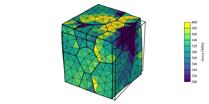
Stress field (\(\sigma_{33}\)) at 1% axial strain (displacement field is exaggerated 10x for illustrative purposes).
Printing Intermediary Results
While the forces output is written at all increments, nodal and elemental results are only written at the end of steps. To get intermediary results, it is therefore necessary to declare several steps. This can be done with the changes highlighted below.
The content of the resulting Simulation Directory (.sim), simple_simulation.sim, is:
simple_simulation.sim
├── inputs
│   ├── simulation.cfg
│   └── simulation.msh
└── results
  ├── elts
  │   ├── ori
  │   │   ├── ori.step0
  │   │   ├── ori.step1
  │   │   └── ori.step2
  │   ├── strain
  │   │   ├── strain.step0
  │   │   ├── strain.step1
  │   │   └── strain.step2
  │   └── stress
  │       ├── stress.step0
  │       ├── stress.step1
  │       └── stress.step2
  └── nodes
      └── coo
          ├── coo.step0
          ├── coo.step1
          └── coo.step2
The deformed mesh can be plotted using Neper:
$ neper -V simple_simulation.sim -step 1 -showtess 1 -showcell 0 -showedge "domtype==1" -dataedgerad 0.005 -dataedgetrs 0.5 -datanodecoofact 10 -showelt1d all -dataelt1drad 0.005 -dataelt3dedgerad 0.0025 -dataelt3dedgecol 32:32:32 -imagesize 800:400 -loop STEP 1 1 2 -step STEP -datanodecoo coo -dataeltcol strain33 -dataeltscale 0.005:0.015 -dataeltscaletitle "Strain [-]" -print strainSTEP -dataeltcol stress33 -dataeltscale 200:400 -dataeltscaletitle "Stress [MPa]" -print stressSTEP -endloop
$ convert strain1.png strain1-scale3d.png -gravity East -composite deformed_mesh_strain1.png
$ convert strain2.png strain2-scale3d.png -gravity East -composite deformed_mesh_strain2.png
$ convert stress1.png stress1-scale3d.png -gravity East -composite deformed_mesh_stress1.png
$ convert stress2.png stress2-scale3d.png -gravity East -composite deformed_mesh_stress2.png
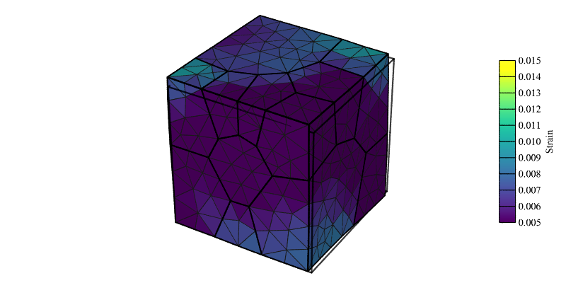
Strain field (\(\epsilon_{33}\)) at 0.5% axial strain (displacement field is exaggerated 10x for illustrative purposes).
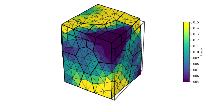
Strain field (\(\epsilon_{33}\)) at 1% axial strain (displacement field is exaggerated 10x for illustrative purposes).
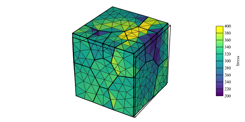
Stress field (\(\sigma_{33}\)) at 0.5% axial strain (displacement field is exaggerated 10x for illustrative purposes).

Stress field (\(\sigma_{33}\)) at 1% axial strain (displacement field is exaggerated 10x for illustrative purposes).