Simple RVE-type Simulation
Note
Read first: Simple Simulation
A polycrystal containing 20 grains, generated and meshed by Neper, is used:
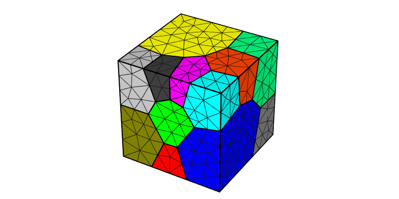
The domain is a unit cube. Length units are assumed to be mm, thus, all pressure units assumed to be MPa for the simulation (including input parameters). An FCC material with Anisotropic Elasticity and the Base Model for plasticity is considered, with the following material parameters:
\(C_{11}\) [MPa] |
\(C_{12}\) [MPa] |
\(C_{44}\) [MPa] |
\(m\) [-] |
\(\dot{\gamma_0}\) [1/s] |
\(h_0\) [MPa] |
\(g_0\) [MPa] |
\(g_s\) [MPa] |
|---|---|---|---|---|---|---|---|
\(245.0 \times 10^3\) |
\(155.0 \times 10^3\) |
\(62.5 \times 10^3\) |
0.05 |
1.0 |
200.0 |
210.0 |
330.0 |
As the domain is a cubic “(representative) volume element”, and if the aim is to apply uniform loading, it makes particular sense to define the loading in terms of strain rate, target strain and maximal strain increment instead of the standard velocity, target time and maximal time increment. The simulation described in Simple Simulation, can then be run using a simplified Configuration File (simulation.cfg) file, as described (and highlighted) below.
Specifying a Strain Rate (set_bc strainrate), etc.
Note
As the set_bc strainrate condition only act on the \(v_z\) components, additional set_bc vel conditions are still required to fix rigid-body motions.
Execution and simulation results are the same as in Simple Simulation. The deformed mesh is reproduced for completeness:
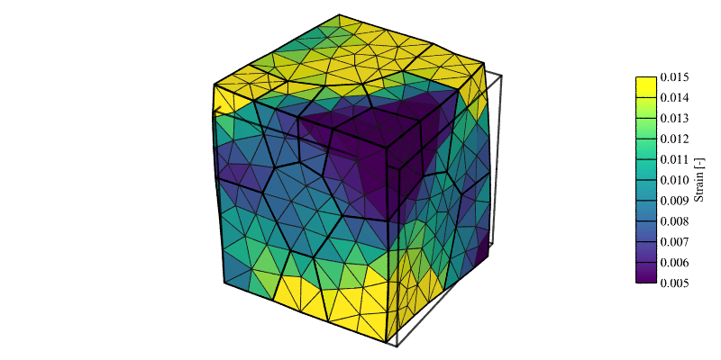
Strain field (\(\epsilon_{33}\)) at 1% axial strain (displacement field is exaggerated 10x for illustrative purposes).
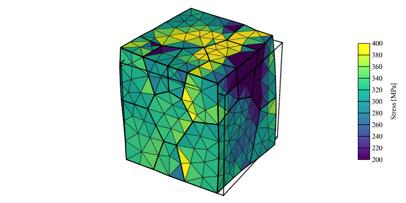
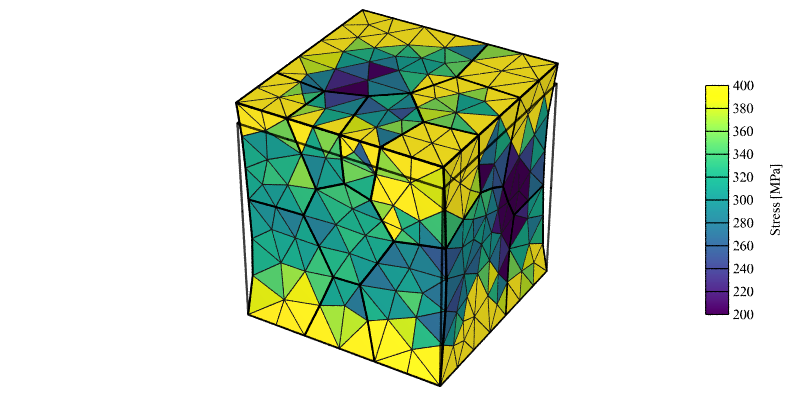
Stress field (\(\sigma_{33}\)) at 1% axial strain (displacement field is exaggerated 10x for illustrative purposes).
Grip Boundary Conditions (grip)
Grip boundary conditions, which can be activated using the grip statement, are different in the sense that they fully constrain the reference and loading faces by prescribing zero velocities in the directions different from the loading direction. Different strain and stress field result, especially close to the reference and loading faces.
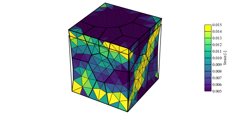
Strain field (\(\epsilon_{33}\)) at 1% axial strain (displacement field is exaggerated 10x for illustrative purposes).
Stress field (\(\sigma_{33}\)) at 1% axial strain (displacement field is exaggerated 10x for illustrative purposes).