Cruciform Specimen Simulation
Note
Read first: Simple Simulation
The domain is a cruciform polycrystalline specimen for biaxial loadings, generated by Neper:
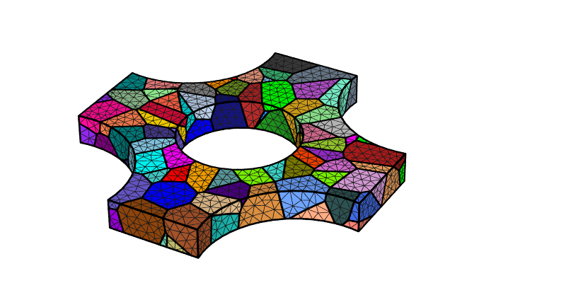
The specimen has (maximal) dimensions of 1, 1 and 0.1 along \(x\), \(y\) and \(z\), respectively.
The same material behavior as in Simple Simulation is used.
The specimen is subjected to biaxial loading, with different biaxiality rates applied via different sets of velocities along the two in-plane directions (\(x\) and \(y\)). Choice is made to apply opposite velocities on the opposite surfaces, while the rigid-body motion along \(z\) of a specific node is blocked. The nodal coordinates, the elemental orientations, stresses and strains at final time (\(t = 5\text{ s}\)) are written to file.
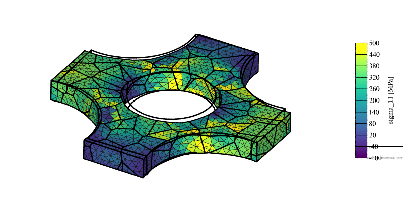
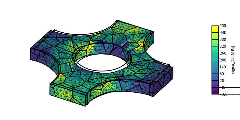
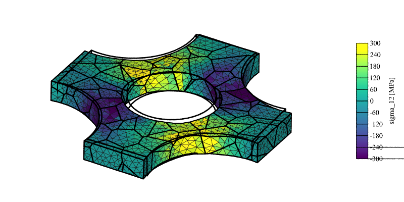
Equal Biaxial
The input is:
simulation.msh(16 partitions)
The results can be plotted using Neper:
$ neper -V cruciform_specimen_simulation.sim -cameraprojection orthographic -cameralookat 0.6:0.6:z -showelt1d all -dataelt1drad 0.003 -dataelt3dedgerad 0.001 -dataelt3dedgecol 32:32:32 -cameraangle 18 -imagesize 800:400 -showelt3d none -showelt1d "domtype==1" -dataelt1dtrs 0.5 -imageformat pov:objects -print mesh -showelt3d all -showelt1d all -includepov mesh.pov -imageformat png -step 1 -datanodecoo coo -datanodecoofact 3 -dataeltscale -100:500 -dataeltscaletitle "sigma_11 [MPa]" -dataeltcol stress11 -print stress11 -dataeltscaletitle "sigma_22 [MPa]" -dataeltcol stress22 -print stress22 -dataeltscale -300:300 -dataeltscaletitle "sigma_12 [MPa]" -dataeltcol stress12 -print stress12
$ for i in 11 22 12; do convert stress$i.png stress$i-scale3d.png -gravity East -composite cruciform_specimen_simulation/stress${i}_field.png; done
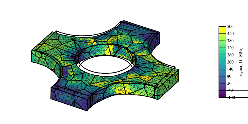
\(\sigma_{11}\) stress field (displacement field is exaggerated 3x for illustrative purposes).
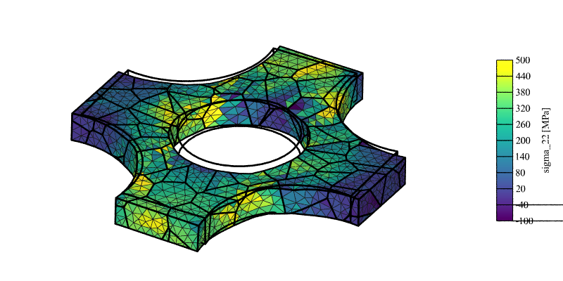
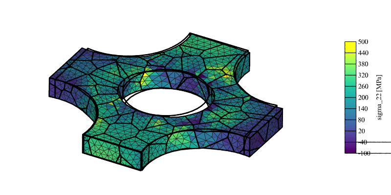
\(\sigma_{22}\) stress field (displacement field is exaggerated 3x for illustrative purposes).
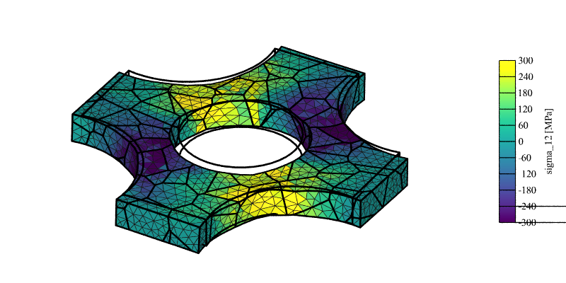
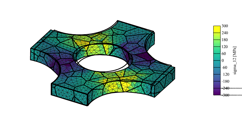
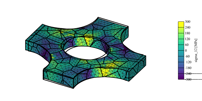
\(\sigma_{12}\) stress field (displacement field is exaggerated 3x for illustrative purposes).
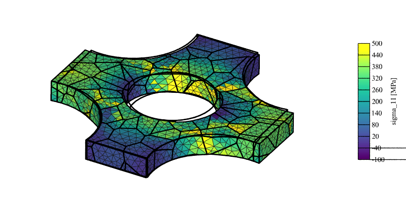
General Biaxial
The (strain) biaxiality rate can be modified by prescribing different velocities along \(x\) and \(y\). For velocities twice as small along \(y\) as along \(x\), the input is:
### FEPX Configuration File

## Material Parameters

    number_of_phases 1

    phase 1

      crystal_type FCC

      c11 245.0e3
      c12 155.0e3
      c44  62.5e3

      m 0.05d0
      gammadot_0 1.0d0

      hard_type isotropic
      h_0 200.0
      g_0 210.0
      g_s 330.0

## Boundary Conditions

    set_bc vel x0 x      -0.01
    set_bc vel x1 x       0.01
    set_bc vel y0 y      -0.005
    set_bc vel y1 y       0.005
    set_bc vel cut1x0z0 z 0

## Steps

    target_time 1
    dtime 0.01

## Printing Results

    print coo
    print ori
    print stress
    print strain
The fields become:
\(\sigma_{11}\) stress field (displacement field is exaggerated 3x for illustrative purposes).
\(\sigma_{22}\) stress field (displacement field is exaggerated 3x for illustrative purposes).
\(\sigma_{12}\) stress field (displacement field is exaggerated 3x for illustrative purposes).
For zero velocities along \(y\) (and still the same velocities along \(x\)), the input is:
### FEPX Configuration File

## Material Parameters

    number_of_phases 1

    phase 1

      crystal_type FCC

      c11 245.0e3
      c12 155.0e3
      c44  62.5e3

      m 0.05d0
      gammadot_0 1.0d0

      hard_type isotropic
      h_0 200.0
      g_0 210.0
      g_s 330.0

## Boundary Conditions

    set_bc vel x0 x      -0.01
    set_bc vel x1 x       0.01
    set_bc vel y0 y       0.
    set_bc vel y1 y       0.
    set_bc vel cut1x0z0 z 0

## Steps

    target_time 1
    dtime 0.01

## Printing Results

    print coo
    print ori
    print stress
    print strain
The fields become:
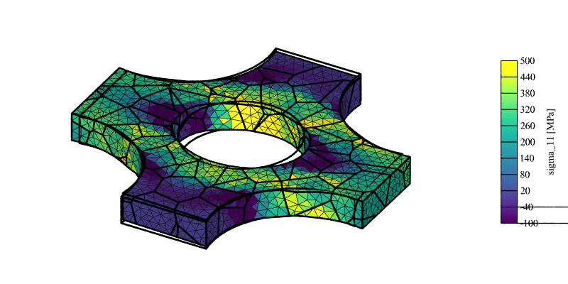
\(\sigma_{11}\) stress field (displacement field is exaggerated 3x for illustrative purposes).
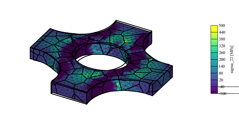
\(\sigma_{22}\) stress field (displacement field is exaggerated 3x for illustrative purposes).
\(\sigma_{12}\) stress field (displacement field is exaggerated 3x for illustrative purposes).
Note that a non-zero (average) \(\sigma_{22}\) stress remains. It could be relaxed by removing the velocity conditions along \(y\) altogether, but greater consistency with the previous conditions can be obtained using Multi-Point Constraints (MPCs), by making so that the \(y\) faces remain in the same plane (hence, \(\sigma_{22} = 0\) on average, while all nodes of the \(y\) surfaces have the same velocity along \(y\)). The input is:
### FEPX Configuration File

## Material Parameters

    number_of_phases 1

    phase 1

      crystal_type FCC

      c11 245.0e3
      c12 155.0e3
      c44  62.5e3

      m 0.05d0
      gammadot_0 1.0d0

      hard_type isotropic
      h_0 200.0
      g_0 210.0
      g_s 330.0

## Boundary Conditions

    set_bc vel x0 x      -0.01
    set_bc vel x1 x       0.01
    set_bc vel cut1x0z0 z 0

    set_mpc vel y0 x
    set_mpc vel y1 x

## Steps

    target_time 1
    dtime 0.01

## Printing Results

    print coo
    print ori
    print stress
    print strain
The fields become:
\(\sigma_{11}\) stress field (displacement field is exaggerated 3x for illustrative purposes).
\(\sigma_{22}\) stress field (displacement field is exaggerated 3x for illustrative purposes).
\(\sigma_{12}\) stress field (displacement field is exaggerated 3x for illustrative purposes).